Specifications
VVR27
VVR27 Specifications Sheet
(Download PDF )
(Download PDF )
VVR150HP
VVR150HP (special applications)
Volume can be customized
Extreme low & high temperatures
(Download PDF )
Volume can be customized
Extreme low & high temperatures
(Download PDF )
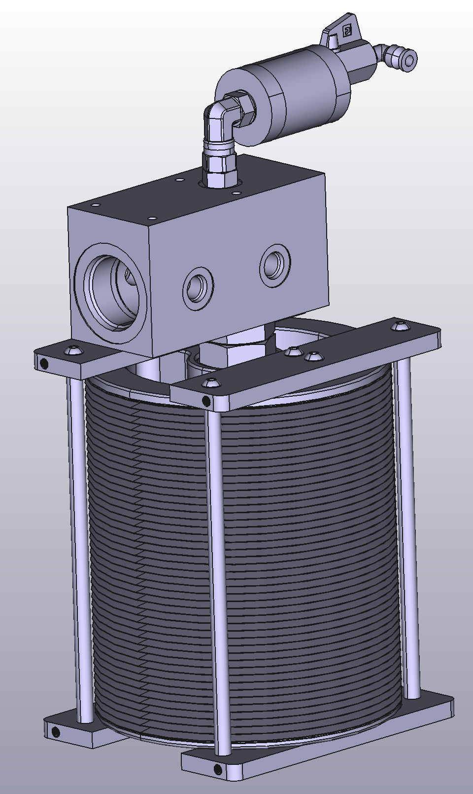
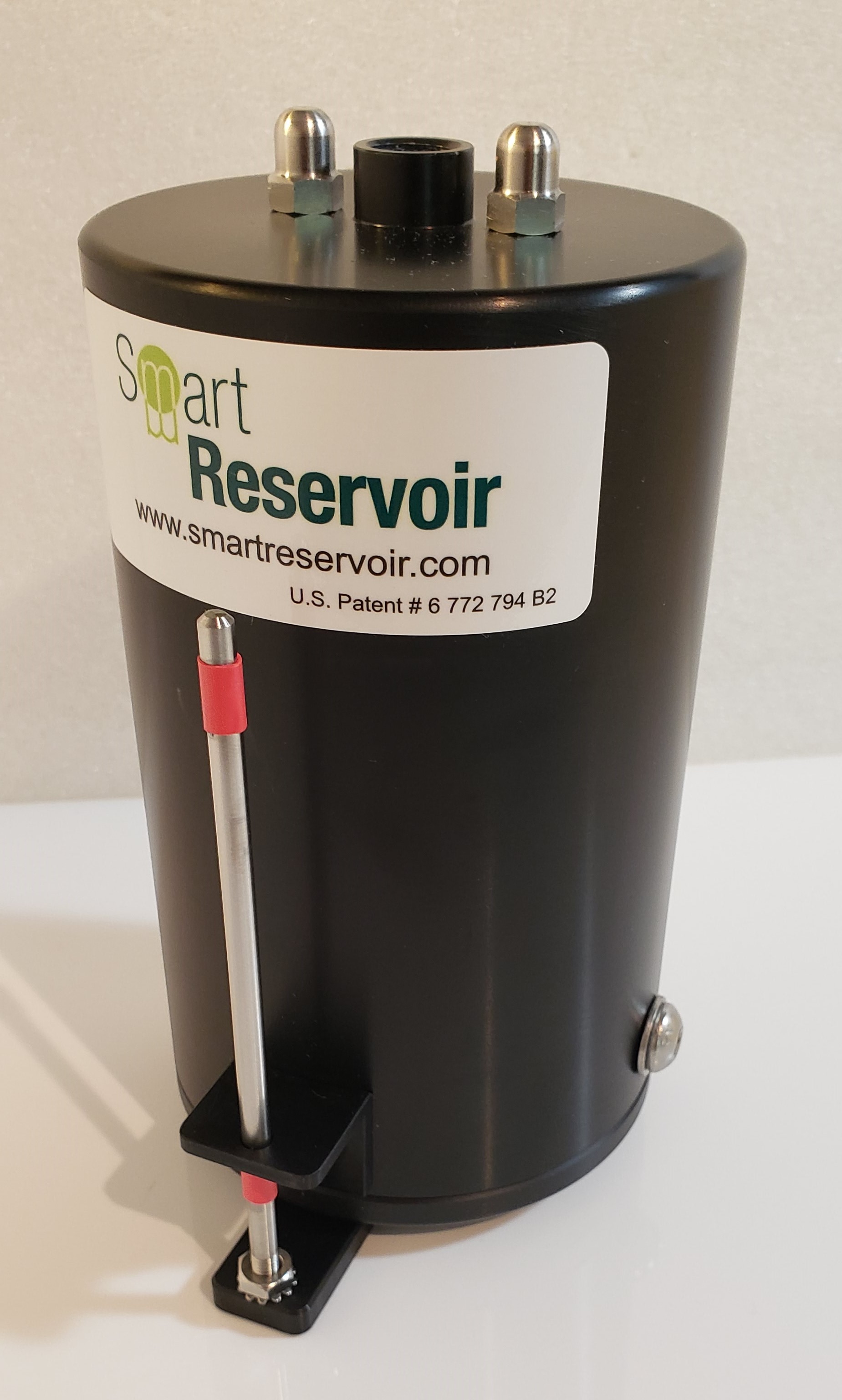
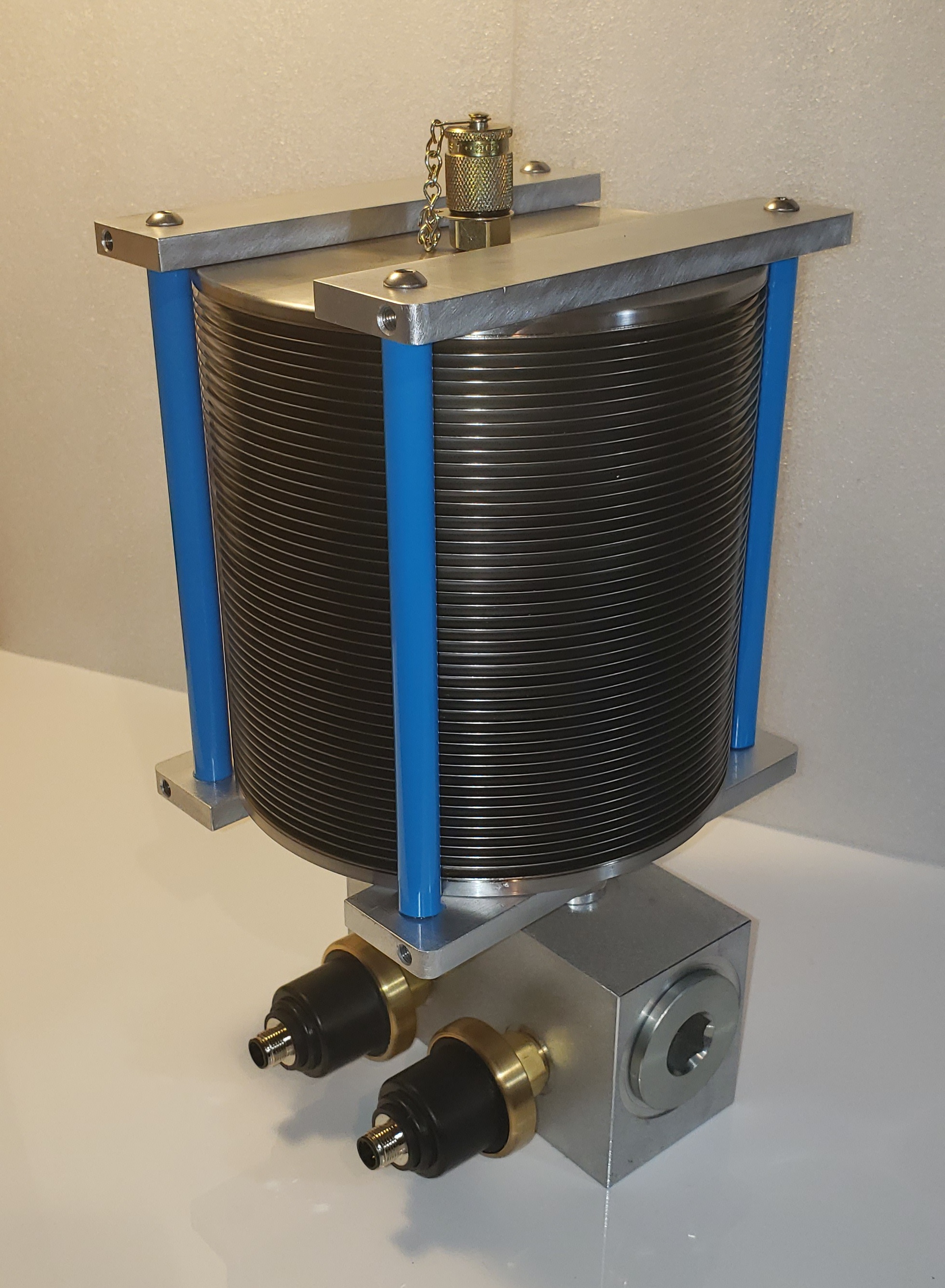
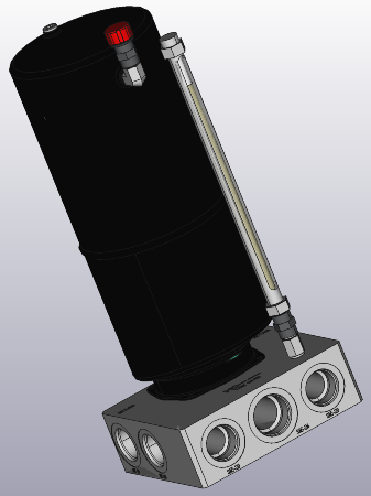
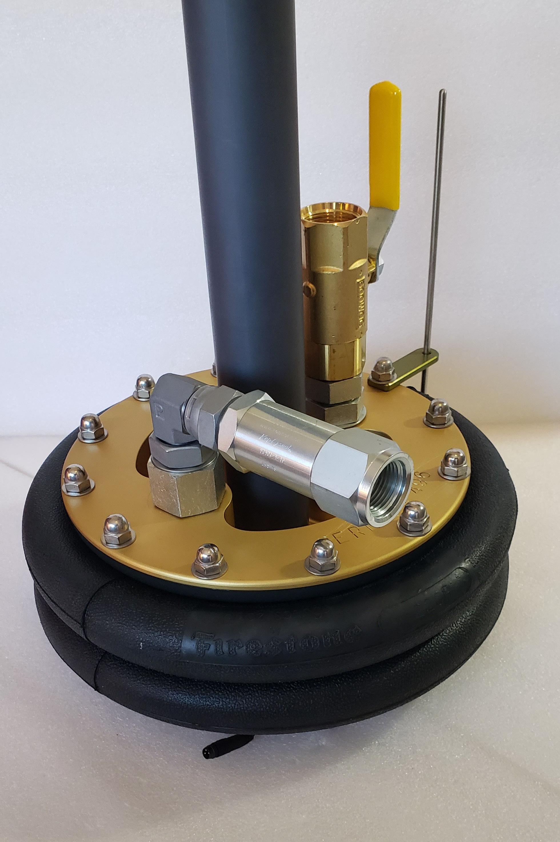
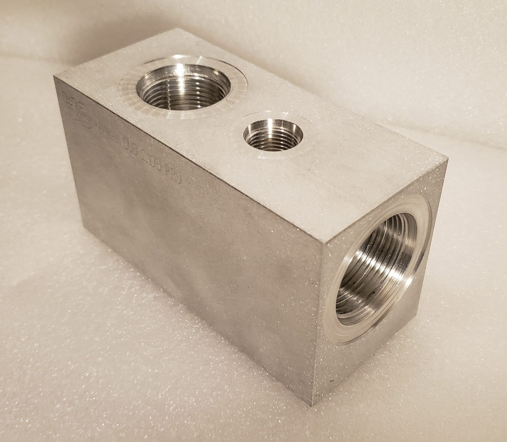
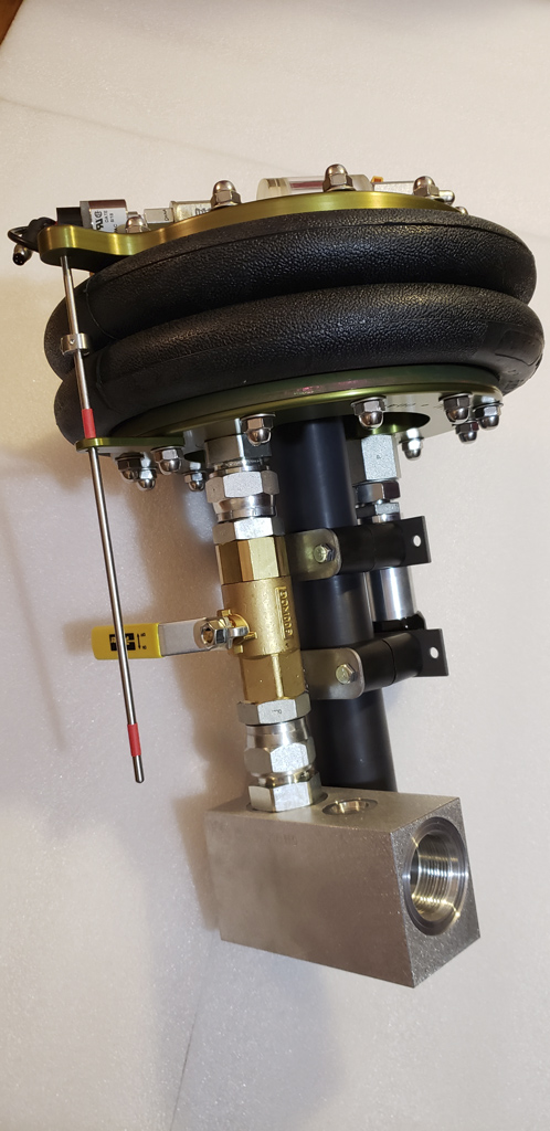
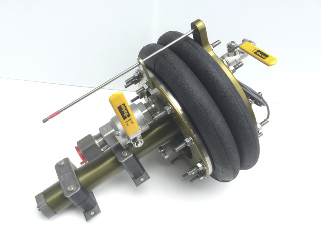
VVR150HP-IM
Flow through instrumentation manifold with air bleed valve assembly.
Can accommodate;
Flow through instrumentation manifold with air bleed valve assembly.
Can accommodate;
- Pressure sensor or pressure switches for level monitoring & alarms
- Over pressure valve
- Dry disconnect network fill coupler
- Temperature indicator
VVR150LP
VVR150LP Specifications Sheet
(Download PDF )
(Download PDF )
VVR180
VVR180 Specifications Sheet
(Download PDF )
(Download PDF )
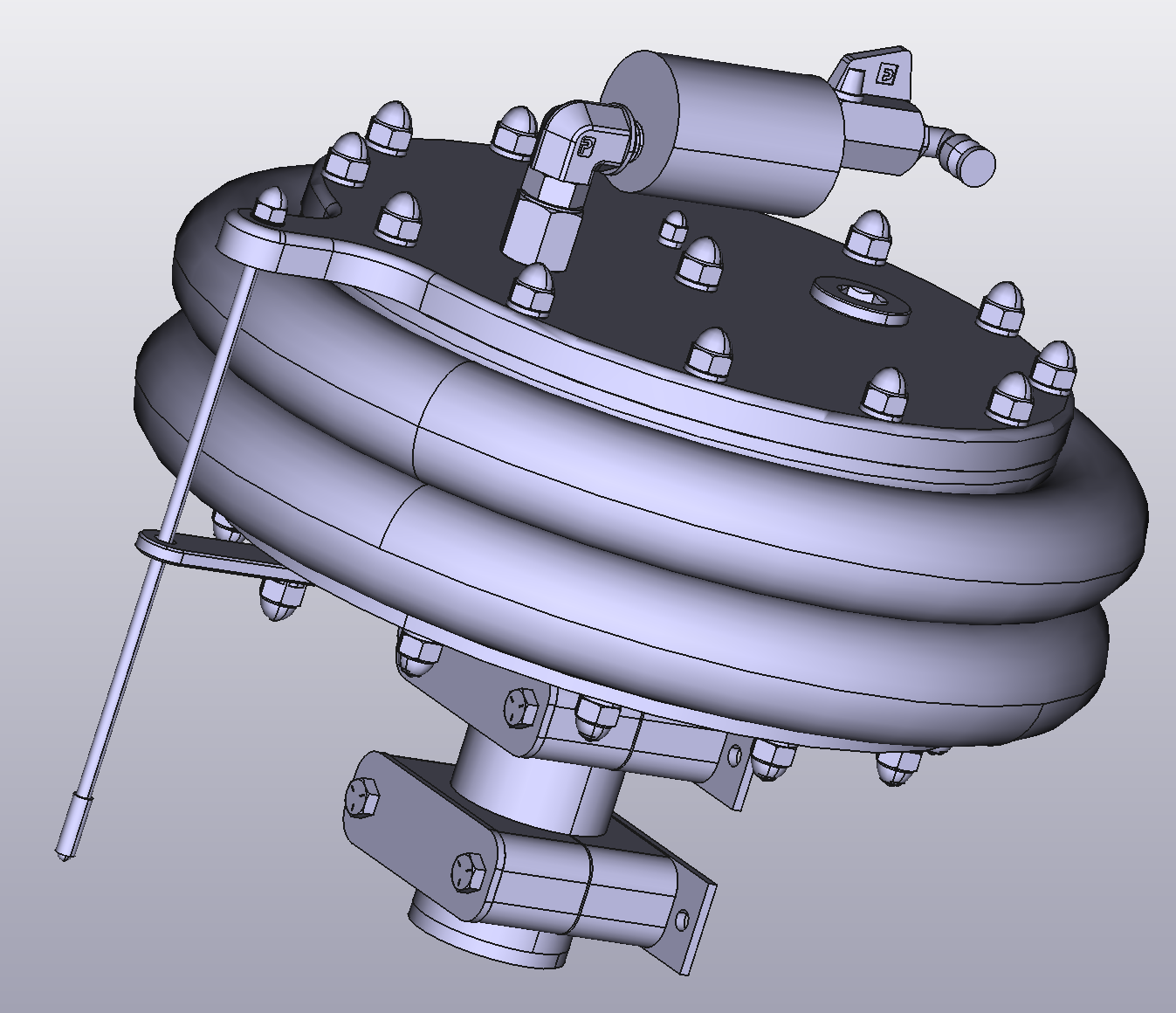
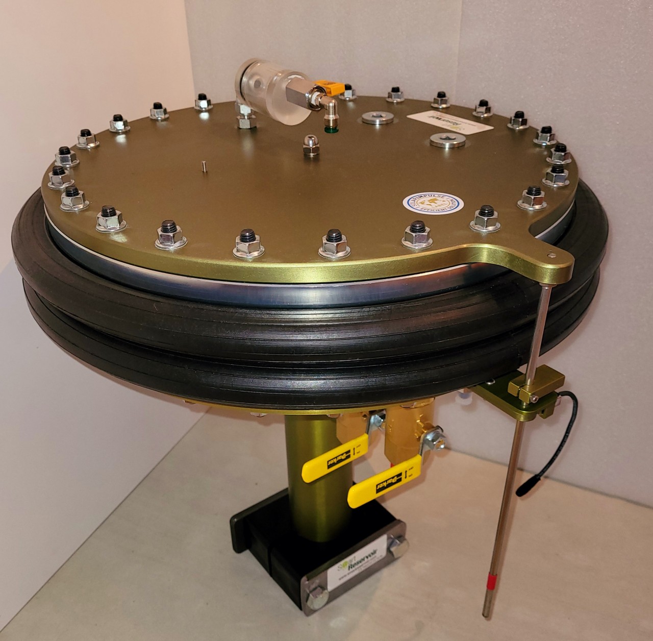
VVR400
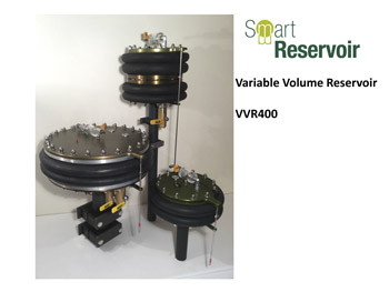
VVR400 Specifications Sheet
(Download PDF )
(Download PDF )

VVR400
VVR800

VVR800 Specifications Sheet
(Download PDF )
(Download PDF )

VVR800-BV-LSM8-AC (800 in3 / 14 liters) with same VVR400 options
VVR1300
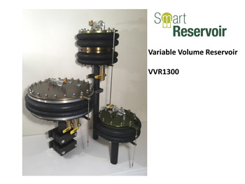
VVR1300 Specifications Sheet
(Download PDF )
(Download PDF )
VVR1300-BV-LS1M8-AC-R (1300 in3 / 21 liters)
10L Atmospheric reservoir
10L Atmospheric reservoir specifications sheet
(Download PDF )
(Download PDF )
Overboard relief valve
VVR400-BV-LSM8-R standard model + overboard relief valve (10 psi / 0.7 bar)
Interface manifold
VVR with interface manifold. Bridge between return line and pump inlet.
Offshore & Subsea units

Offshore & Subsea VVR400 (Pressure compensator)
Low level switch
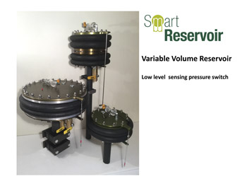
Low level sensing pressure switch
(Download PDF )
(Download PDF )
Adjustable low level pressure switch
Fill pumps


Network fill DC pump
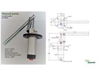
Fill pump (Download PDF )
It is highly recommended to install a manual (or electric) pump near the VVR. This pump can be used for level make-up following a component replacement or due to system leakage. Smart Reservoir can also supply a compact and affordable 12 or 24 Vdc filling/kidney loop unit (please ask for a quote). We can also supply you a complete kidney loop system with an electric pump for larger system fill or for constant filtration of the fluid during operations. Please use the following circuit layout for such system.Heating pad & misc.
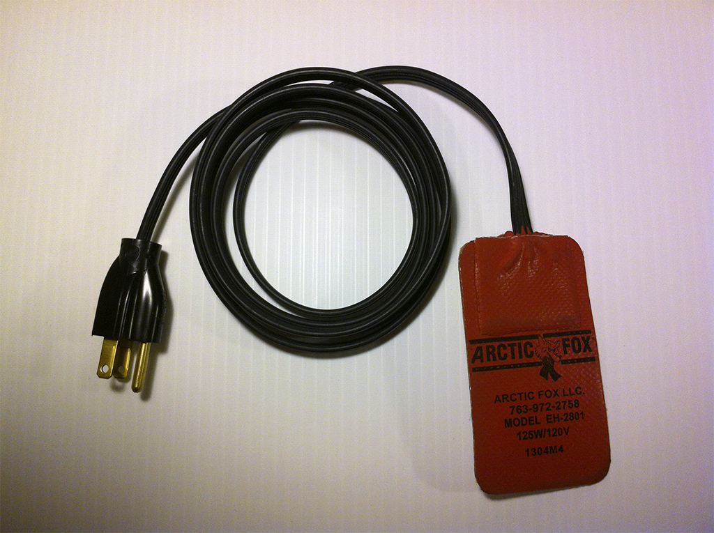
Heating pad
When extreme cold temperatures are encountered (-20°C and lower), a stick-on heating pad can optionally be installed on the VVR inner cavity. The addition of this heater will keep the temperature above the low operating range of the unit. To reduce the warm-up time by half, two heating pads could also can be installed (T= 5-6 hours or 2-3 hours)
Ratings:
For VVR400: 125 watts / 120 VacFor VVR800: 250 watts / 120 Vac
For VVR1300: one or two 250 watts / 120 Vac
12 & 24 Vdc units also available
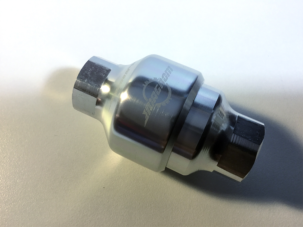
Drain line magnetic filter